|
SummaryThe H-1 is an experimental rocket engine I am currently developing. It will generate 20 pounds of thrust at full throttle, powered by liquid gasoline and gaseous oxygen. H-1 will serve as a test engine to help learn more about manufacturing methods, the engineering process, and safety/operations standards in the aerospace industry.
The H-1 is currently pending further design reviews and will hopefully be manufactured in 2021.
|
Temperature ControlTemperature is the biggest enemy of any rocket engine. Since there is no concern for flight weight, and to facilitate the use of easy-to-machine materials, an active cooling system is used on the H-1.
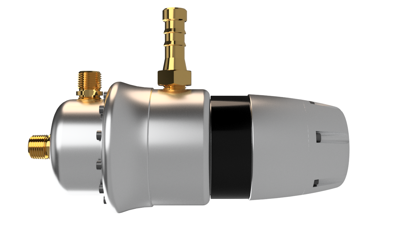
The main component of the cooling system is the cooling shell, pictured to the right. It will direct chilled water around the combustion chamber and nozzle, as well as other critical components such as the injector face.
There is only 0.03 inches between the outer wall of the combustion chamber and the inner wall of the cooling shell. The thin flow of water, paired with a high flow rate of 0.6 gallons per minute through the system will ensure adequate cooling.
The warmed water is expelled from the engine along with the exhaust, to protect the area below the test stand from damage. It also protects against any dangers from uncombusted fuels.
|
|
While water may be enough to cool the engine for brief use, longer burns may lead to degradation of the nozzle, which will reach more than 5,000 degrees Fahrenheit during operation.
To further cool the engine, it is run in a "fuel rich" configuration. 50% more fuel is injected into the combustion chamber than needed, which mixes with exhaust gasses and cools them.
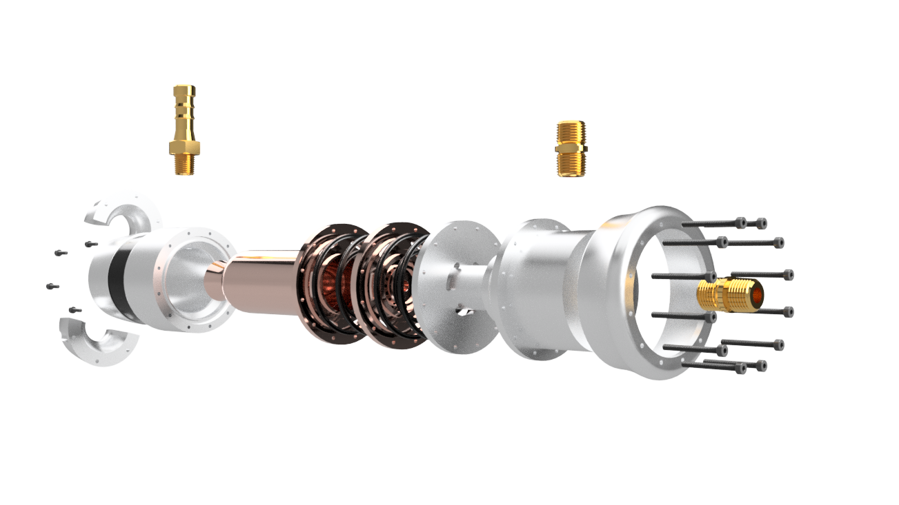
For assembly purposes, the cooling shell is split into three pieces; two identical leaves that surround the nozzle, and the main body of the cooling shell. The cooling shell main body also makes up the structural backbone of the engine, and provides the mounting point for the engine to the test stand.
Combustion ChamberThe combustion chamber is the heart of the engine, where fuel and oxidizer is mixed. On the H-1, the combustion chamber and the nozzle are machined from a single piece of copper to aid in heat transfer to the surrounding water.
The combustion chamber connects through a flange to the cooling shell to transfer thrust.
The injector is installed in a taper at the top of the combustion chamber, and sealed to the top of the combustion chamber using a series of bolts and Quattro gaskets.
|
|
|
|
InjectorLike the combustion chamber, the injector is made of copper to help with heat transfer. It is primarily cooled by the oxygen and fuel flowing through it, but there are also channels for water to flow up from the cooling shell through the flange.
Oxygen flows directly through the center of the injector into the combustion chamber through a single orifice, just under 0.125 inches in diameter. The fuel runs through a a series of 16 holes, each 0.03 inches across, that are angled to collide with the flow of oxygen 0.25 inches from the face of the injector. This style of injector, known as an impinging stream, helps to ensure a good mixture of fuel and oxygen, while also coating the walls of the chamber in the excess fuel to aid in cooling.
|
DistributorThe distributor connects to the top of the injector, and routes the fuel and oxygen lines from the feed system to their respective spots on the injector.
To make manufacturing easier, the distributor is made of two aluminum pieces that are sealed with Quattro gaskets and a series of bolts.
The distributor also has a protective aluminum sheath attached that covers the edges of the flanges of the combustion chamber and injector. While this part is not necessary for the operation of the engine, it does provide some protection to personnel after a hot fire, covering the parts of the engine that are the hottest.
|
|